计算机体系结构
本章将在第1至3章中构建的所有芯片整合起来,集成为一台通用计算机,使之能够运行用机器语言编写的程序。
背景知识
存储程序概念
存储程序概念的基本思想其实相当简单:计算机基于固定的硬件平台,能够执行固定的指令集。同时,这些指令能够被当成构件模块,组成任意的程序。
不同于1930年以前的机械计算机,这些程序的逻辑并没有被嵌入到硬件中,而是被存储到计算机的存储设备(memory)里,跟数据一样,成为所谓的“软件(softwoare)”。 因为计算机的操作是通过当前正在执行的软件来向用户展示其功能,所以每次向计算机中载入不同的程序时,同样的硬件平台可以实现完全不同的功能。
冯诺依曼架构
存储程序概念是很多抽象的、应用型计算机模型的关键,其中最著名的是通用图灵机(1936)和冯•诺依曼机(1945)。图灵机是描述虚拟的简单计算机的抽象机,主要用来分析计算机系统的逻辑基础。相比之下,冯•诺依曼机是实际应用型的体系结构,它几乎是今天所有计算机平台的基础。
冯•诺依曼体系结构的基础是一个中央处理单元(CPU,Central Processing Unit),它与记忆设备(memory device) 即内存”进行交互,负责从输入设备(input device) 接收数据, 向输出设备(output device)发送数据。
这个体系结构的核心是存储程序的概念:计算机内存不仅存储着要进行操作的数据,还存储着指示计算机运行的指令。

内存
冯•诺依曼机的内存中存有两种类型的信息:数据项(data items)和程序指令(programming instructions)。
对这两种信息通常采用不同的方式来处理,在某些计算机里,它们被分被别存储到不同的内存区中。尽管它们具有不同功能,但两种信息都以二进制数形式存储在具有通用结构的随机存储器中(一个连续的固定宽度的单元阵列,也称为字即word,或者存储单元,每个单元都有一个独立的地址)表示。因此,一个独立的字(代表一个数据项或者一条指令)通过它的地址来指定。
中央处理器
CPU 是计算机体系的核心,负责执行已被加载到指令内存中的指令。这些指令告诉 CPU 去执行不同的计算,对内存进行读/写操作,以及根据条件跳转去执行程序中其他指令。
CPU 通过使用三个主要的硬件要素来执行这些任务:算术逻辑单元(ALU,Arithmetic-Logic LInit),一组寄存器 (registers)和控制单元 (control unit)。
- 算术逻辑单元(ALU) ALU 负责执行计算机中所有底层的算术操作和逻辑操作。
- 寄存器(Registers)CPU 的设计是为了能够快速地执行简单计算。为了提高它的性能,将这些和运算相关的数据暂存到某个局部存储器中是十分必要的,这远比从内存中搬 进搬出要好。因此,每个CPU 都配有一组高速寄存器,每个寄存器都能保存一个单独的字。
- 控制单元(Control Unit) 计算机指令用二进制代码来表示,通常具有16、32或64位宽。在指令能够被执行之前,须对其进行解码,指令里面包含的信息向不同的硬件设备(ALU,寄存器,内存)发送信号,指使它们如何执行指令。指令的解码过程是通过某些控制单元(control unit)完成的。这些控制单元还负责决定下一步需要取出和执行哪一条指令。
CPU 操作现在可以被描述成一个重复的循环:从内存中取一条指令(字):将其解码;执行该指令,取下一条指令;如此反复循环。
指令的执行过程可能包含下面的一些子任务:让 ALU 计算一些值,控制内部寄存器,从存储设备中读取一个字,或向存储设备中写入一个字。在执行这些任务的过程中,CPU 也会计算出下一步该读取并执行哪一条指令。
寄存器
内存访问是很慢的过程。寄存器也能提供同样的数据访问功能,但没有来回的数据传递和寻址开销。
首先,寄存器位于CPU 芯片内部,所以对它们的访问几乎可以瞬间完成:其次,与数百万个内存单元相比,寄存器数量非常少。因此,机器语言指令可以使用短短的几个位就能指定要操作的寄存器在什么位置,这样指令格式也更短。
基于不同的目的,不同的CPU 采用不同数量、不同类型的寄存器。
- 数据寄存器(Data registers) 这些寄存器为 CPU 提供短期记忆(memory)服务。
- 寻址寄存器(Addressing registers) 为了进行读写,CPU 必须连续访问内存中的数据。这样我们必须确定被访问的内存字(word)所在的内存地址。在某些情况下这个地址 作为当前指令的一个部分给出,而其他某些情况下它依赖于前面一条指令的执行结果。对于后者,这个地址应该被存储到某个寄存器中,使得该寄存器的内容在今后的操作中能够 被当作存储单元的地址——这就需要用到寻址寄存器。
- 程序计数寄存器(Program counter register) 执行程序时,CPU 必须总是知道下一条指令在指令内存中的地址。这个地址保存在一个特殊的寄存器即程序计数器中(或称 PC, Program Counter)。
Hack 平台硬件规范详述
Hack 平台是 16-位冯•诺依曼机,包括一个 CPU、两个独立的内存模块(指令内存和数据内存)和两个内存映像IO 设备(屏幕和键盘)。这个体系结构中的某些部分—一尤 其是它的机器语言——曾在第4章中介绍过。为了便于参考,这里给出了这些内容的概要。
Hack 的CPU 由第2章介绍的 ALU 和三个分别称数据寄存器(D,data register)、地址寄存器 (A,address register)、程序计数器(PC,program counter)的寄存器组成。
计算机体系结构以这样的方式来进行连接:PC(程序计数器)芯片的输出端被连接到 ROM 芯片的地址输入端。如此一来,ROM芯片总是输出 ROM[PC](大小为一个 word),即“PC所指向的指令内存单元”的地址。这个值称为当前指令(current instruction)。那么,每个时钟周期内整个计算机的操作可以表示为:
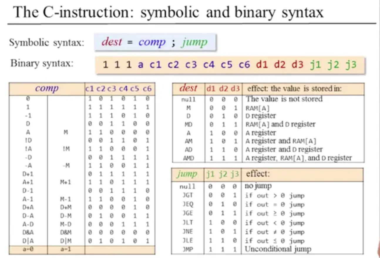
- 执行(Execute):当前指令中不同的bit 位域被同时被送入计算机中不同的芯片。如果其是地址指令(即 MSB=0),则A寄存器被置为指令中内含的15-位常数。如果其是计算 指令(即 MSB=1),则指令中内含的a-位域、c-位域、d-位域和-位域被当作是控制位,导致 ALU 和寄存器会相应的去执行该指令。
- 取指令(Fetch):计算机下一步取哪一条指令,取决于当前指令的jump 位和 ALU 的输出。这些值共同决定了是否去执行跳转。如果是要执行跳转,则PC被置为A 寄存器的 值:否则就将PC的值加1。在下一个时钟周期,PC指向的指令在 ROM 的输出中出现,如此不断循环。

实现


中央处理器
CPU 的实现目标是建立逻辑门结构,其能够执行指定的Hack 指令和读取下一条要执行的指令。

上图中没有给出的部分是CPU 的控制逻辑,用来执行下面的任务:
- 指令解码 (Instruction decoding):解析出指令所代表意思(指令的功能)。
- 指令执行(Instruction execution):发信号指示计算机的各个部分应该做什么工作来执行指令(指令的功能)。
- 读取下一条指令 (Next instruction fetching):指出下一步执行哪一条指令(指令的功能以及 ALU 的输出)。
计算机

项目
Memory
/**
 * The complete address space of the Hack computer's memory,
 * including RAM and memory-mapped I/O.
 * The chip facilitates read and write operations, as follows:
 *     Read:  out(t) = Memory[address(t)](t)
 *     Write: if load(t-1) then Memory[address(t-1)](t) = in(t-1)
 * In words: the chip always outputs the value stored at the memory
 * location specified by address. If load==1, the in value is loaded
 * into the memory location specified by address. This value becomes
 * available through the out output from the next time step onward.
 * Address space rules:
 * Only the upper 16K+8K+1 words of the Memory chip are used.
 * Access to address>0x6000 is invalid. Access to any address in
 * the range 0x4000-0x5FFF results in accessing the screen memory
 * map. Access to address 0x6000 results in accessing the keyboard
 * memory map. The behavior in these addresses is described in the
 * Screen and Keyboard chip specifications given in the book.
 */

CHIP Memory {
    IN in[16], load, address[15];
    OUT out[16];

    PARTS:
    // Put your code here:
    //address[14],address[13]
    //00 选RAM
    //01 选RAM
    //10 选Screen
    //11 选Keyboard
    //正好可以用一个 DMux4Way来区分

    DMux4Way(in = load, sel = address[13..14], a = loadR1, b = loadR2, c = loadS, d = loadK);
    Or(a = loadR1, b = loadR2, out = loadR); // 00、01都是RAM16K

    //回顾RAM 的接口
    RAM16K(in = in, load = loadR, address = address[0..13], out = outR);
    Screen(in = in, load = loadS, address = address[0..12], out = outS);
    Keyboard(out = outK); //没有load...

    //最后再根据选择的芯片,对应选择谁的输出
    Mux4Way16(a = outR, b = outR, c = outS, d = outK, sel = address[13..14], out = out);
}
CPU

/**
 * The Hack Central Processing unit (CPU).
 * Parses the binary code in the instruction input and executes it according to the
 * Hack machine language specification. In the case of a C-instruction, computes the
 * function specified by the instruction. If the instruction specifies to read a memory
 * value, the inM input is expected to contain this value. If the instruction specifies
 * to write a value to the memory, sets the outM output to this value, sets the addressM
 * output to the target address, and asserts the writeM output (when writeM = 0, any
 * value may appear in outM).
 * If the reset input is 0, computes the address of the next instruction and sets the
 * pc output to that value. If the reset input is 1, sets pc to 0.
 * Note: The outM and writeM outputs are combinational: they are affected by the
 * instruction's execution during the current cycle. The addressM and pc outputs are
 * clocked: although they are affected by the instruction's execution, they commit to
 * their new values only in the next cycle.
 */
CHIP CPU {

    IN  inM[16],         // M value input  (M = contents of RAM[A])
        instruction[16], // Instruction for execution
        reset;           // Signals whether to re-start the current
                         // program (reset==1) or continue executing
                         // the current program (reset==0).

    OUT outM[16],        // M value output
        writeM,          // Write to M?
        addressM[15],    // Address in data memory (of M)
        pc[15];          // address of next instruction

    PARTS:
    //// Replace this comment with your code.
    Mux16(a=instruction, b=outALU, sel=instruction[15], out=inA);

    Not(in=instruction[15], out=notinstruction);
    Or(a=notinstruction, b=instruction[5], out=loadA);
    ARegister(in=inA, load=loadA, out=outA, out[0..14]=addressM, out=PCin);

    And(a=instruction[15], b=instruction[3], out=writeM);
    Mux16(a=outA, b=inM, sel=instruction[12], out=outAM);

    DRegister(in=outALU, load=instruction[4], out=outD);

    // If not instruction then return D in ALU
    And(a=instruction[11], b=instruction[15], out=zx);   // default 0
    And(a=instruction[10], b=instruction[15], out=nx);   // default 0
    Or(a=instruction[9], b=notinstruction, out=zy);      // default 1
    Or(a=instruction[8], b=notinstruction, out=ny);      // default 1
    And(a=instruction[7], b=instruction[15], out=f);     // default 0
    And(a=instruction[6], b=instruction[15], out=no);    // default 0

    ALU(x=outD, y=outAM,
        zx=zx, nx=nx, zy=zy, ny=ny, f=f, no=no,
        out=outALU, out=outM,
        zr=zero, ng=negative);

    Or(a=negative, b=zero, out=notpositive);
    Not(in=notpositive, out=positive);

    And(a=instruction[2], b=negative, out=jump0);
    And(a=instruction[1], b=zero, out=jump1);
    And(a=instruction[0], b=positive, out=jump2);
    Or(a=jump0, b=jump1, out=jump01);
    Or(a=jump01, b=jump2, out=jump012);
    And(a=jump012, b=instruction[15], out=jump);

    PC(in=PCin, reset=reset, load=jump, inc=true, out[0..14]=pc);
}
Computer
/**
 * The Hack computer, consisting of CPU, ROM and RAM.
 * When reset = 0, the program stored in the ROM executes.
 * When reset = 1, the program's execution restarts.
 * Thus, to start running the currently loaded program,
 * set reset to 1, and then set it to 0.
 * From this point onwards, the user is at the mercy of the software.
 * Depending on the program's code, and whether the code is correct,
 * the screen may show some output, the user may be expected to enter
 * some input using the keyboard, or the program may do some procerssing.
 */
CHIP Computer {

    IN reset;

    PARTS:
    //// Replace this comment with your code.
    ROM32K(address=pc, out=instruction);
    CPU(inM=memOut, instruction=instruction, reset=reset, outM=outM, writeM=writeM, addressM=addressM, pc=pc);
    Memory(in=outM, load=writeM, address=addressM, out=memOut);
}